
About • Process • Components • Add-On Components • Denitrification • Testing/Maintenance
About the Aquarobic Maxi-Plant™
 The Maxi-Plant™ series (Sequencing Batch Reactor) treats wastewater flows from 5,000 to 100,000 gallons per day. Maxi-Plant™ units perform consistently better than most “secondary” wastewater treatment plants. Advanced “tertiary” treatment is achieved through our Maxi-Plant™ systems’ add-on components. The unique aerobic up-flow and re-circulating filters enable a higher degree of treated effluent (<5 mg/L BOD & SS).
Disinfection or nitrate/phosphorus removal components are also available. Outstanding test results were obtained after comprehensive six (6) months testing programs. Maxi-Plant™ units are sold completely factory assembled in fiberglass tanks and ready to install, or as a “kit” allowing the system to be installed onto pre-fabricated or locally constructed concrete tanks. The entire unit may be buried with only access hatches and electrical control panels visible, not detracting from the aesthetic appearance of the site while contributing to its security. The “MM” (Class 1) series has an additional up-flow or a re-circulating filter and disinfection unit with additional compartments to enable higher degrees of treatment. This system blends itself to daily continuous usage.
Most frequent applications for Maxi-Plant™ series include:
- Small communities
- Parks, camps, golf course/recreational clubs
- Restaurants & other commercial facilities (i.e., shopping centers, motels)
- Repair failing systems
- Resort hotels
- Condominiums
- Schools
Aquarobic Maxi-Plant™ Process Description
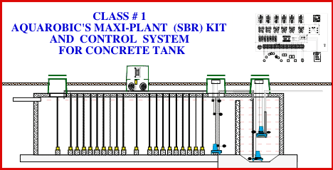
In order to achieve optimum clarity of the treated effluent, the system works on a periodic fill and draw principle (Sequential Batch Process). During day and night hours, raw sewage enters the aeration surge tank chamber. This chamber is sized to hold the daily wastewater flow, plus a minimum 50% safety margin; the system only processes one batch every 4 hours, or 1/6 of the daily wastewater flow. This gives the system the ability to handle the occasional shock load without any detrimental effect on the effluent quality.
Every 4 hours the transfer pump (P-1) pumps for 30 minutes from the aeration chamber filling the clarifier chamber with mixed liquor until it reaches the weir and overflows back to the aeration chamber, thus skimming off floatables for further treatment. Then a 3 hour perfectly quiescent period follows. (Note that during this period there is no movement in the clarifier).
After the 3 hour settling period, the effluent pump (P-2) which is suspended half way up in the clarifier chamber, starts and transfers the clear supernatant to the drip irrigation pump chamber leaving 1/2 of the volume in the bottom for the sludge return pump (P-3). When the liquid reaches a predetermined level, a float switch stops the effluent pump (P-2) and starts the sludge return pump (P-3) transferring the remaining settled sludge to the front end of the aeration chamber for additional biological digestion. Immediately, another 4-hour cycle is initiated for six cycles per day.
It is important to point out, that the sequencing batch process of this system is not affected by flow variations. The sewage is retained in the large aeration surge chamber and only a predetermined volume is transferred to the clarifier chamber every 4 hours. There is no need to worry about peak flows or design peak flow.
During periods of low flow, a low level float switch prevents transfer pump (P-1) from starting, allowing the system to skip one or several cycles. In addition, the air compressors can be programmed to operate at intermittent time cycles, saving energy during low flow periods.
Aeration/Surge Chamber (Treatment Compartment)
This compartment has a capacity of 100% of the calculated daily flow, plus a minimum 50% safety margin. The sewage is continuously exposed to the finely diffused air bubbles. Each regenerative ring compressor is treated to provide a minimum of 2100 cubic feet of air per pound of BOD5, at the maximum water depth possible. The air blowers are highly efficient centrifugal design resulting in only a “whisper” sound level and low power consumption. All air piping and porous air diffusers are fabricated from non-corrosive materials. The length to width ratio of the aeration/surge chamber coupled with air diffusers being spaced evenly across the chamber creates a series of air curtains which make it virtually impossible for any short circuit to take place.
Clarifier Chamber
The capacity of the clarifier chamber must equal 2 times the designed batch size or 1/6 the daily calculated flow rate. The system uses this compartment to separate the solids from the clear supernatant and uses time to accomplish the separation.
Aquarobic Maxi-Plant™ Factory Built Components
- The Maxi-Plant’s™ equipment package comes completely assembled and wired. Field assembly consists of installing the air diffusers system, fiberglass manway(s) and inter-connecting electrical wires to the control panel.
Standard electrical requirements for the Maxi-Plant TM series:
From 5,000 to 15,000 gallons per day:
1 phase, 60 Hz., 230 volt, 2 hot wires plus a neutral and a ground wire,
From 15,000 to 85,000 gallons per day:
3 phase, 230/460 volt, 60 Hz., 3 hot wires plus a neutral and a ground.
- The timer, alarm and control system on all units are always 115 volts single phase powered.
 Design Parameters: 100 gallons per person per day or 400 gallons per residence (using standard flush toilets).
- 2100 cubic feet of air per pound of BOD5 and an estimated 0.17 lb. of BOD5 per person per day.
- Three hours of uninterrupted settling prior to discharge in situations involving heavy seasonal use.
- Water saving devices are necessary for the formula assumption.
Aquarobic Maxi-Plant™ Add On Components
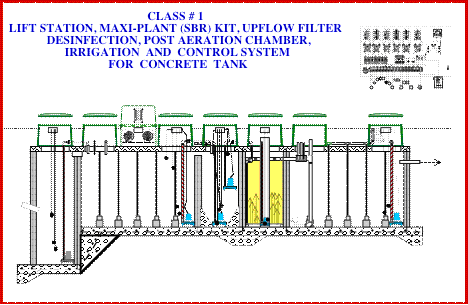
Up-Flow Filter
The clear supernatant which was transferred out of the clarifier chamber by transfer pump # 2 is pumped down to a perforated manifold at the base of the up-flow or recirculating filter chamber where the effluent rises slowly upward through the filter media. At the top of the filter the polished clear liquor then overflows by gravity through a Chlorinator to the last chamber where the effluent can be used for toilet flushing, lawn watering and other non-potable uses.
At the end of the filter cycle, the remaining fluid in the up-flow filter is returned to the front aeration chamber by the backwash pump # 4 which is located in a perforated well tile in the center of the filter chamber. The rapid return rate flushes back accumulated solids from the filter and as the liquid is removed, air re-enters around the filter media thus maintaining a healthy aerobic biomass to reduce the pollution load from incoming batches.
Aquarobic Maxi-Plant™ Denitrification Process
The process for removal of nitrogenous compounds in wastewater may be easiest described as two separate biological reactions although they are frequently interrelated.
The first step is designed to convert ammonia nitrogen and organic nitrogen into Nitrate Nitrogen. This process (Nitrification) is a result of certain bacteria being able to oxidize ammonia to nitrate nitrogen. These bacteria (Nitrosomonas and Nitrobacter) require aerobic conditions in order to procreate. The Aquarobic modular advanced wastewater treatment plants have been found highly effective in supporting biological nitrification resulting in a conversion to nitrate. This is primarily due to the ideal conditions existing in the plant”s aeration chamber, i.e. highly dissolved oxygen concentration and long retention time.
In the second process step, denitrification is accomplished with the use of another group of bacteria (Psuedomonas, micrococcus, archromabacter and Bacillus.) These bacteria require anoxic conditions (without free oxygen) During this condition period they use the nitrate nitrogen as an oxygen source, thus reverting the nitrate nitrogen to gaseous nitrogen, which then escapes into the atmosphere.
The rate of denitrification is minimized in the presence of free oxygen. Denitrification can occur at diminished rates if anoxic conditions have previously existed during which enzyme synthesis may occur. It is, however, generally agreed that the level of dissolved oxygen should approach zero in order to achieve consistently good performance.
Since it has been proven that the two bacteria groups can in fact, live together, it then becomes a matter of proper timing of the air supply cycles and control of sludge production in order to obtain optimum performance.
Aquarobic Maxi-Plant™ Testing / Maintenance
Testing
In conjunction with the Ontario Ministry of Environment, NSFI completed testing the Aquarobic denitrification unit’s capabilities. The results are published in NSFI’s June 1994 report entitled research study, Aquarobic Aerobic Sewage Treatment System with Denitrification. The executive summary of this report states:
“…The unit was able to achieve significant denitrification resulting in effluent nitrate levels consistently less than 4 mg/l (overall mean 4.5 mg/l), while generally maintaining CBOD, levels below 30 mg/l. Influent tkn levels averaged approximately 40 mg/l, while effluent tkn plus nitrate-nitrogen concentrations averaged below 3 mg/l. In limited sampling, effluent nitrite levels were generally non-detectable and some removal of dissolved phosphate species was observed through the overall unit.”
Maintenance
- Weekly inspection suggestion list
- An explicit Operation and Maintenance Manual is supplied.
- By-products of the process are water, CO2, and a residue of inert materials such as coffee grounds, etc. This materials will accumulate over a period of time, and removal by a septic tank hauler once every 2-3 years may be required