
About • Process Description • Components • Add-On Components • System Operation
About the Aquarobic Mini-Plant™
The Mini-Plant™ series (Sequencing Batch Reactor) treats wastewater flows from 500 to 5,000 gallons per day. The Mini-Plant™ tank is sized to hold a volume of three (3) times the daily wastewater flow, providing 100% or more overload capacity. Mini-Plant™ units have undergone stress-loading tests and performed consistently better than most “secondary” wastewater treatment plants.
 Advanced “tertiary” treatment is achieved through our Mini-Plant™ systems’ add-on components. The unique aerobic up-flow and re-circulating filters enable a higher degree of treated effluent (<5 mg/L BOD & SS – Class 1A). Disinfection or nitrate/phosphorus removal components are also available. Outstanding test results were obtained after comprehensive six (6) months testing programs at a national testing service both for the Aquarobic International, Inc. Mini-Plant™ and the Mini-Plant™ and filter system. The results exceeded all the requirements of the highest rating and have been certified as such under national and international standards. Test results available upon request.
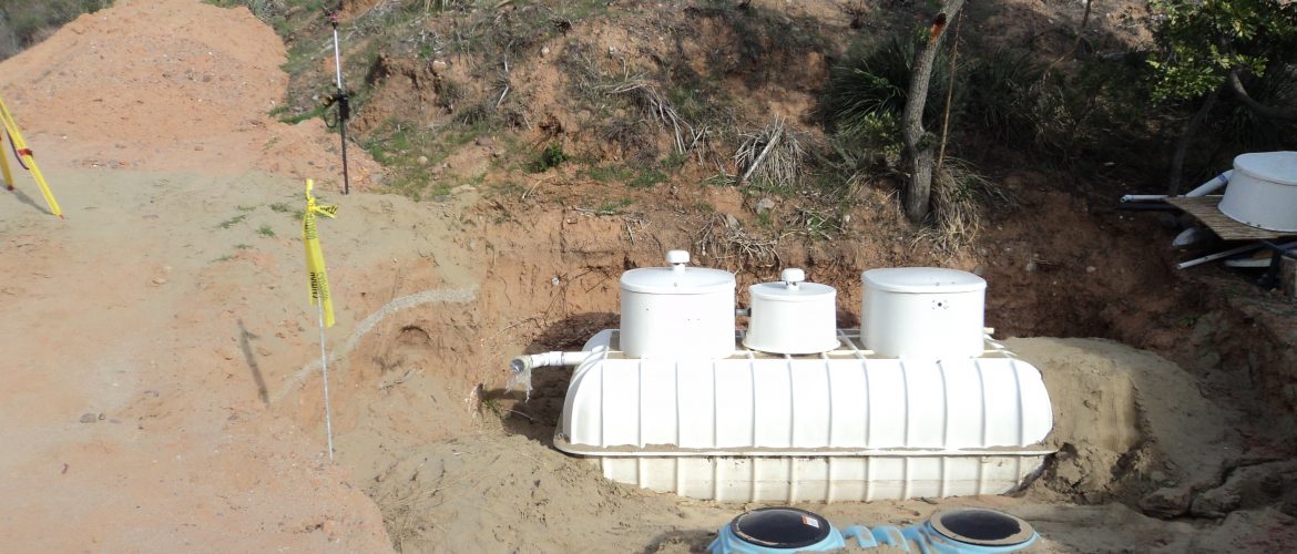
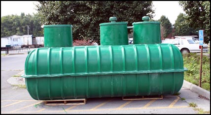
Mini-Plant™ units are sold completely factory assembled in fiberglass tanks and ready to install, or as a “kit” allowing the system to be installed onto pre-fabricated or locally constructed concrete tanks. Normal operating cycle’s power consumption for a 600 GPD is 8.5 kilowatts per day.
Most frequent applications for Mini-Plant™ series includes:
- Single family residences
- Parks, camps, golf course/recreational clubs
- Small commercial facilities
- Repair failing systems
Aquarobic Mini-Plant™ Process Description
 The Mini-Plant™ is a Sequential Batch Reactor (SBR) system, controlled by a factory set programmer which times aeration and settling functions. A batch of treated effluent is discharged to the disposal area once a day.
The program is set to aerate for 20 hours, 6:00 A.M until 2 A.M., supplying the wastewater with fine diffused air. Air diffusers create thousands of fine air bubbles supplying oxygen for the aerobic digestion process. At 2:00 A.M. the program turns the compressor off and a 3 hour quiescent settling period follows. During this period, the aeration tank becomes the settling tank and the batch process uses this time to separate the solids from the clear supernatant.
After the Mini-Plant’s™ 3 hours of perfectly quiescent settling period, the clear supernatant (effluent) is discharged (5:00 A.M. to 6:00 A.M.) to the disposal area, solids are retained. The Mini-Plant™ begins the new day’s cycle, aerating to further digest the retained organic solids and the incoming wastewater. The Mini-Plant™ has three main sections; the control panel, the manway and the tank with its in tank components.
Aquarobic Mini-Plant™ Components
Manways
- Manufactured from heavy fiberglass reinforced polyester. They protect and provide access to the air compressors, electrical junction boxes and the mechanical connections. Inside the manway, energy efficient ring type air compressors are mounted. The level sensors and submersible pump are also wired to the junction box.
Air Compressor(s)
- Regenerating energy efficient ring type supplying up to 52 cubic feet of air per minute to the diffusers operating on 230 volts, 60 Hz. variable hp./ amps depending on load required results.
Control Panel
- The panel box is both UL and CSA approved type 3 enclosure suitable for outdoor / indoor mounting. It contains contactors, motor starters, program timer, control relays, alarm buzzer, and junction block. A separate circuit breaker load center panel is mounted onto the bottom of the Aquarobic control panel. The load center panel is UL listed with a main ratings 120 / 240 / Volts AC. 3-wire 125 Amp. With 8 poles, normally with a 20 amp double breaker 240 volts for the blower and pump power, a 15 amp single phase breaker 115 volts for the control circuit and another 15 amp single phase breaker 115 volts for the alarm circuit.
A 230-volts single-phase supply line (3 wires with ground # 10 gauge.) from the main power source. A control panel schematic guides the qualified serviceman or electrician to troubleshoot any part of the system. A visual, audible, and remote signal are provided to monitor and ensure continuous proper operation.
Aquarobic Mini-Plant™ Add On Components
Re-Circulating Filter
 The filter is installed in a separate fiberglass tank or in a “kit” form to install onto a locally built two compartment concrete tank. The effluent from the Mini-Plant is pumped into a 4″ distribution manifold at the top of the filter material (on the bottom, 12″ to 16″ of 2″ washed stone topped off with 24″ to 30″ of 3/4″ washed stone). The effluent flows slowly down through the filter media where it is collected by another 4″ perforated pipe manifold at the bottom of the filter material and flows to the center 18″ PVC re-circulating filter pump well. A pre-determined volume allowance in the center well activates the re-circulating pump switch, which starts to pump the liquid around and back into the top 4″ perforated manifold for continuous filtering, dispersing the daily amount slowly.
The filter tank is designed to hold the daily wastewater flow from the Mini-Plant, in the empty space above the filter, and in the filter media.
The UV light is always “on” intensifying the bacterial kill. Because the effluent is discharged once per day, treatment time can be extended to further polish the effluent. The re-circulating pump line’s restricting valve can be adjusted to create back-pressure on the line forcing some of the re-circulating liquid out through a small pipe that leads to the UV disinfection system. The restriction valve determines the effluent amount circulating in the disinfection area. Depending on the size of the unit, an adjustment to affect the flow of less than one gallon per minute can increase the treatment time and efficiency of the UV.
- Advantages of the Aquarobic Mini-plant™ Up-flow or Re-circulating Filter Units:
- Tertiary treatment producing high quality effluent. (Less than 5-5 BOD5 and Suspended Solids (SS.)
- The entire operation is automatically programmed for the specified hydraulic flow pattern of each application.
- Plastic Spin Clean – Available in 3/4″, 1″, 1 1/2″, and 2″ sizes with unique self-cleaning spinning action that cleans the stainless steel screens even under the most severe conditions. Maximum 150 PSI pressure rating.
- Steel Spin Clean – 2″ through 12″ epoxy-coated carbon steel, with sintered stainless steel screens. Spin cleaning action ensures efficient handling of the most difficult filtration problems agriculture, industrial, wastewater and large turf systems operating at 100 to 2800 GPM.
- T Filter – Low profile design with black or clear debris basin, having a 3/4″ MPT drain with cap to suit a wide range of applications.
- Screens – Replacement screens in appropriate mesh sizes are available for all API filters or Aquarobic International, Inc. The Mini-Plant uses a 50 -micron filter.
Effluent Disposal
In most cases, the Commonwealth of Virginia permits the effluent from the Mini-Plant recycling filter units to surface discharge after disinfection. The treated effluent can be pumped to pressure or vacuum lines for transporting to a community disposal area or used on the property for irrigation.
Aquarobic Mini-Plant & trade and Filter Bed System
Aquarobic International, Inc. raised filter bed disposal system is designed to complement the Mini-Plant.
The application rate to the top of the filter bed:
Flows up to 1500 gpd: = 4 gal. /Sq.Ft./day
Flows than 1500 gpd. Domestic, commercial / industrial =2.5 gal. / Sq. ft./day.
- The distribution grid (4″ perforated pipe) is to be placed level, on 15″ centers in 12″ of washed 3/4″ inch stone.
- The maximum size of any filter bed top is 900 sq. ft. larger areas require multiple beds separated by a minimum distance of 15′ using a common contact and mantle area.
- The elevated portion of the filter bed is a minimum of 30″ inch depth. The filter media is specified by Aquarobic International, Inc.
- Whenever possible the contact area is to be cut into the ground (level + or -6″), and back-filled with a minimum of 12″ of a sandy material, 0.5 to 1.5 mm clean sharp sand. On sloping land a 12″ separation distance is required by the State of Virginia (VDH) to the limiting zone, no cutting will be allowed; imported leveling material is used for the mantle area. This material is to be from soil type II or III and back filled with 12″ of mason sand with an average size of 1 to 2mm. If the high ground water table is only 12″ from the ground surface, heavy clay material must be used around the perimeter of the filter bed mason sand mantle area to prevent breakout.
The contact and mantle area is sized by the following formula:
| A = QT/25. | A = contact and mantle area. Q = quantity of wastewater per day—daily sewage flow T = the percolation time of the original soil in minutes/inch (of the “a” horizon). Percolation rates above 120 min./inch, the mantle area is to be sized at an application rate of no more than 0.20 gallons per square foot per day. |
- At a minimum, the mantle shall be at least as wide as to equal the footprint of the filter bed material and extending to a minimum of 50 feet from the outer distribution pipes in the direction of flow. Other separation distances (e.g.. well, property line, buildings, etc.) shall be measured from the toe of the filter bed.
Aquarobic Mini-Plant™ System Operation
The Mini-Plant™ is a Sequential Batch Reactor (SBR) system programmed by a factory set timer, which regulates aeration, settling and pump functions. The system discharges a batch of aerobically (highly treated effluent averaging 7 BOD & 11 SS) through a forward flush 100 micron spin filter. The spin filter further reduces the suspended solids to less than 10 ml/l, prior to discharge to the drip irrigation system.
The Aquarobic Mini-Plant™ program aerates for 20 hours a day, supplying the wastewater with fine diffused air from 6 A.M. until 2 A.M. the following morning. At 2 A.M. the program turns off the compressor and a 3 hour quiescent settling period follows. During this period, the aeration tank becomes the settling tank (clarifier) and the batch process uses this time to separate the solids from the clear supernatant.
After the Mini-Plant’s™ perfectly quiescent 3 hours settling period, the clear supernatant (effluent) is discharged (8 minutes “on” and 2 minutes “off” 5 a.m. to 6 a.m.) to the spin filter, further polishing prior to passing through to the K valve and into one of the drip irrigation zones. During the 2 minute “off” period, the K valve switches to the next zone. The process repeats until the low water float switch turns the effluent pump “off” or the one-hour period expires. The tank capacity is always three times the daily wastewater flow.
The Aquarobic International, Inc. / Clearwater drip system forward flushes the spin filter while the pump is activated. Each zone has a 15-pound spring-loaded check valve at the return manifold; as the zone becomes pressurized the check valve opens allowing a continuous forward flushing of the zone back to the front of the Mini-Plant™ tank, for the remaining 8-minute “on” cycle.
The program restarts the daily cycle which further digests both the retained organic solids and incoming wastewater.